Preconstruction: Construction Consulting Services

Site Analysis & Inspections: Regardless of scope, all projects begin with a thorough analysis of the building site to determine the suitability of the property to the proposed construction project, including review of municipal governing agency codes, regulations and zoning requirements.
Preliminary Consulting: Jackson Construction guides the client into the development process and provides insight for planning and implementation of the project. We identify the appropriate site-specific design requirements in order to create the budget parameters. This process will continue throughout the project.
Team Selection & Management: Jackson Construction assists clients in selecting the architectural, engineering, and professional service team best suited to meet their needs based upon project type and compatibility.
Preliminary Project Budget: Jackson Construction works with sub-contractors to produce phased budgets and schedules of hard and soft costs based on preliminary plans. After the establishment of an approved project budget, Jackson Construction provides updated budget reports to clients reflecting all related expenses and changes to the original budget. These updates begin at preconstruction and continue throughout the construction process.
Design & Plan Development: The process of design and plan development has become quite complicated and some would even say "broken." The 1994 Los Angeles earthquake changed Southern California building requirements forever. All new homes built in Southern California today require structural engineering. In 2008, many other counties in California mandated that all new homes built must have structural engineering. The design process became broken when it became necessary to integrate two separate plans. There is the Architectural Plan and there is the Structural Plan. CAD (Computerized Automated Drafting) has only compounded the problems as most computer programs do. The structural plan is supposed to complement the architectural plan however, it has become common to see structural plans that are incompatible with the conception of architectural intent. In fact, it has become common for the architectural plan and structural plan to be two completely different homes. The reason why preconstruction structural elevation drawings are so important is the simple fact that engineers refuse to put dimensions on many parts of their structural plans and details because they don't want to be liable. The good news is, no one is ever held liable for doing the job right. As experienced builders, Jackson Construction will draw the detail, get it approved and build it right the first time.
 "PLAN THE BUILD AND BUILD THE PLAN"
Even if the Architect and Engineer work together, they still won't produce a structural steel plan that can be utilized for bidding or building purposes. Structural steel plans are necessary on larger homes with bigger spans and on glass homes where there is minimal wall space for lateral integrity. We have a saying in construction, "If you can't draw it, you can't build it." Jack specifically went back to college in 1997 to receive a structural steel welding certificate so he could integrate that knowledge into the Architectural and Structural plan. From structural elevation drawings, steel detailers and fabricators are able to produce structural steel plans that can be utilized for bidding and building purposes.
Preconstruction: Structural Elevation Drawings
Preconstruction Structural Elevation Drawings are created by someone with enough concrete, framing and structural steel experience, who is able to look at the Architectural plans and Structural plans at the same time and draw exactly what will be built with dimensions and elevations, both above and below grade. This is not architectural or structural design, all drawings reference the architectural and structural plans and details. The exact location of steel columns and beams must be located on the plan in relationship to the foundation and framing with dimensions and elevations above and below grade. All steel beams, wood beams, and any other connections associated with the steel columns must be drawn with dimensions and elevations. Preconstruction structural elevation drawings with dimensions above and below grade are all the work the Architect and Structural Engineer refuse to do because they don't want to be liable for the actual construction process. Without hard dimension to pull a tape measure from, no one will know what to build. "You can't build a project by driving a stake through a set of plans."
The importance of creating a buildable plan cannot be overstated. To begin a building project with incomplete and incompatible architectural and structural plans is by far the most inefficient and least cost effective way to build. In preconstruction, Jackson Construction works with Architects, Engineers, Contractors and Designers to produce a buildable home plan with correct dimensions and elevations, so your dream home doesn't become your dream nightmare.
The following is an example of the Preconstruction Structural Elevation Drawings completed on the Sharpe Residence with the related pictures of the construction process.
All Preconstruction Structural Elevation Drawings shown were drawn by Jack Phillips.
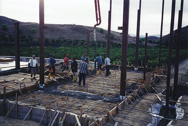
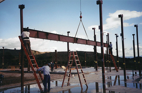
This picture was taken from the back of the Field Room that was poured first because it had a polished concrete floor at the same elevation as the adjacent hardwood floors. The Sharpe Residence was designed with 41 steel columns and 75 steel beams. The Structural Engineer on this project was Bryce Richmond. Jack completed 125 preconstruction structural elevation drawings to bring this home out of the ground. Steel is prefabricated in a welding shop, so the length of column, stud and bolt hole layout, steel beam elevations and connections, base plate dimensions, and all wood beam and framing connections must be pre-determined before fabrication can begin. The elevation and dimensions of all steel saddles to hold wood beams are pre-determined and fabricated in the welding shop. All structural elevation drawings are based on the Structural Engineers details and the Architects elevations. All structural elevation drawings are submitted for Architectural and Engineering approval. Steel fabrication plans are drawn from dimensions shown on structural elevation drawings and approved by the Structural Engineer.
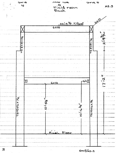
This is the second drawing done of the Tube Steel columns in the back of the Field Room. This drawing shows the exact elevation of the steel columns above finish floor and the elevation of the wood beam connections that must be welded onto the columns in the fabrication shop. This drawing references page A5.3 of the Architectural plan. The dimension from finish floor to the bottom of the base plate of the Tube Steel columns is 40-1/2".
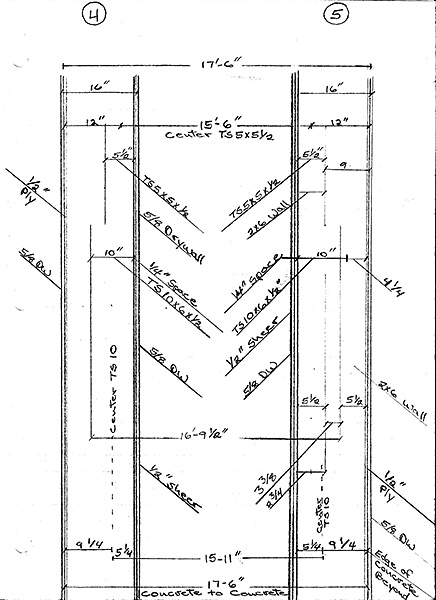
This is the first drawing done to locate the Tube Steel columns in the back of the Field Room. To locate the steel columns in the foundation, first one must locate the framed walls, sheer panel and drywall in relationship to the foundation and then locate the steel columns within those parameters. Notice that every material used to construct the wall has an exact dimension and location in relationship to the foundation dimension of 17'-6".
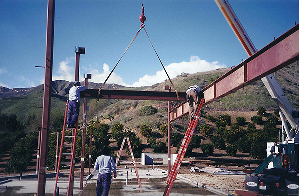
This picture shows Chapala Iron installing the W21x57 beam on Grid line 3.
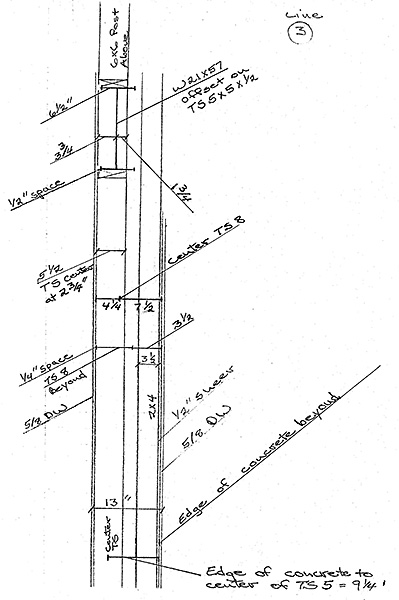
This is the first drawing done to locate the Tube Steel columns and W21x57 beam on Grid line 3. To locate the Tube Steel columns in the foundation, first one must locate the framed walls, sheer panel and drywall in relationship to the foundation and then locate the steel columns and beams within those parameters. Notice that the W21x57 beam had to be offset on the Tube Steel 5x5x1/2" column in order for the W21x57 to be located inside the framed wall structure.
This picture shows Chapala Iron attaching the W12x50 beams onto the Tube Steel 5x5x1/2" columns. Most of the threaded studs to attach wood post to the Tube Steal columns were welded in the shop as shown. Shop welding on a table is a much easier process and more cost effective than welding in the field.
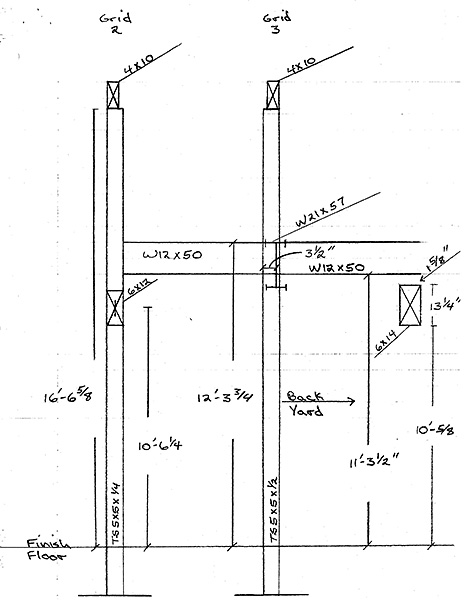
This is the second drawing done to locate the Tube Steel columns and W21x57 beam on Grid line 3. Notice that the W21x57 beam had to be offset on the Tube Steel 5x5x1/2" column in order for the W21x57 beam to be located inside the framed wall structure. The W12x50 beams are shown attached to the W21x57. The right side of the W21x57 beam is inside the ceiling soffit area. All steel and wood beam elevations are shown. The Tube Steel 5x5 columns were set 40-1/2" below finish floor on 3'x3'x12" concrete pads.
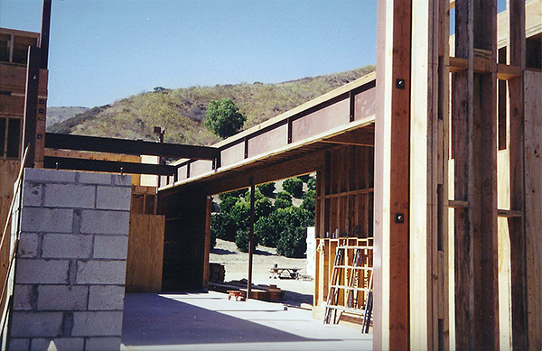
This picture taken during framing shows W12x50 beams attached to the W21x57 beam. The right side of the W21x57 beam is in the ceiling soffit area between the W21x57 and the exterior 6x12 header. The 3x and 4x wood members attached to the Tube Steel columns and beams are shown.
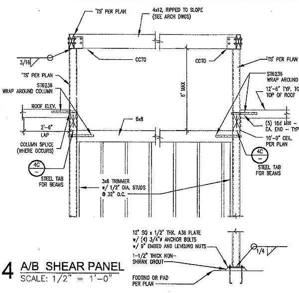
Structural Engineer Detail Drawing 4/S3.1
The Structural Engineer is responsible for structural design however, the Structural Engineer is not responsible for Architectural elevations and dimensions. So this structural detail does not show the length of the Tube Steel columns or the elevation of the wood beams. The entire purpose of structural elevation drawings is to fill in the gaps between the Architectural plans and Structural Engineering plans as to clarify with dimension and elevations, what will actually be built. People that don't plan what they're going to build usually make a lot of mistakes that the owners of the project will end up paying for. If you can imagine, a lot of framers won't even look at the Architectural plans and the Structural plans have no dimensions.
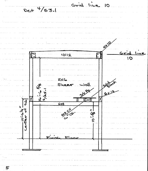
This drawing shows the Tube Steel columns and framing at Grid line 10. As you can see, we have referenced Structural detail 4/S3.1 and all the dimensions and elevations of the Tube Steal and framing connections are shown from finish floor. The length of the Tube Steel is referring to Detail 2 on Architectural page A5.1. So our preconstruction structural elevation drawings are very similar to the engineers detail drawings except, we have put dimensions and elevations on our drawings.
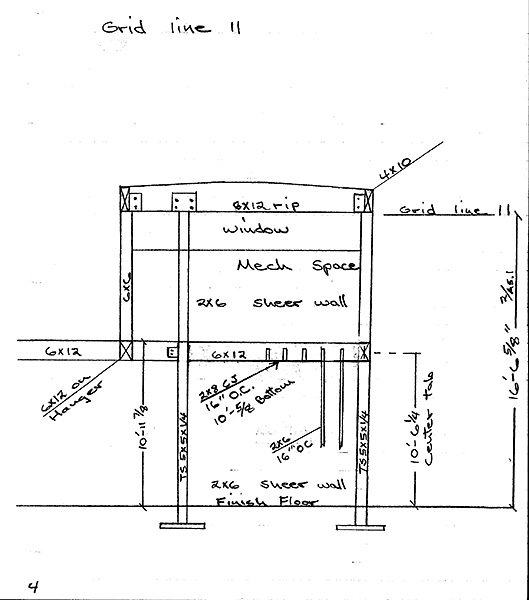
This drawing shows the Tube Steel columns and framing at Grid line 11. All the dimensions and elevations of the Tube Steal and framing connections are shown from finish floor. The length of the Tube Steel below finish floor is 40-1/2", so there is enough information on these drawings to draw steel detail plans for approval and shop fabrication.
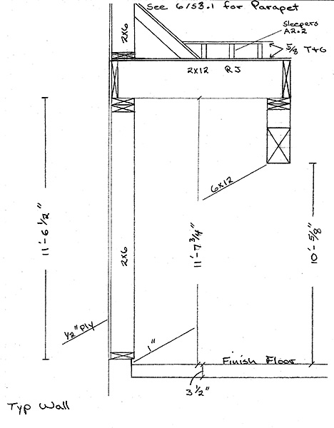
This preconstruction elevation drawing was done to show a cut section through a typical exterior wall with dimensions and elevations.
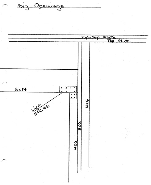
This was a typical large opening on the home. Structural Detail 6 on page S3.2 was similar. Large glass openings have a lot of wind shear. I prefer to have a 2x King Stud so we can face nail the header. The extra 4x6 behind the King Stud runs from the bottom plate thru to the Top plate and gives the 12' high wall and large opening a lot of extra strength. On windy days the 4x6 behind the 2x6 King Stud will stop the wall from shaking and wobbling. A lot of preconstruction is just common sense and the plans and drawings are what ties everyone working on the project together. All these decisions must to be made in preconstruction because the 4x6 post also has a hold down attached to it with a concrete embedded bolt that must be set in the formwork before the foundation is poured and before the framing begins. "Plan the build and build the plan."